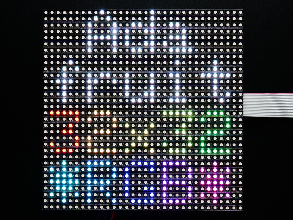

On larger displays, like our 32x32 display, data is clocked in 6 bits at a time: 3 represent a pixel at the top of the panel and 3 represent one at the bottom. Each clock cycle, then, represents one of the 512 pixels of the display. On our 16x32 displays, data is clocked in 3 bits at a time on 3 input lines. To address this, RGB panels are built to allow us to clock in the bits for our red, green and blue LEDs at the same time. Obviously, the more bits we need to clock in, the more slowly this cycle goes. If we repeat these steps quickly enough your eyes won't be able to tell that only one row at a time is lit and the complete image will appear on the display.
#Led matrix panel driver
This enables the latch, allowing the row data to reach the output driver but it also disables the output so that no LEDs are lit while we're switching rows. Pull the latch and output enable pins high.Clock in the data for the current row one bit at a time.

Sure, you could drive all 16 of these LEDs at once, but if you have a matrix of 1024 LEDs you're not going to just clock in all those pixels and latch them out at once because the current consumption would be huge! Instead, the trick is to take advantage of an effect called "persistence of vision" in order to build the image a few pixels at a time by "scanning" your way across the display.įor each row of pixels, we repeat the following cycle of steps: It may be silly to drive 16 LEDs this way, but when you start getting into larger numbers it's incredibly helpful.

Take a moment to study that and then we'll walk through the cycle. I've put together an animation of a single color, 4x4 matrix. To better understand how this shift register business works, let's have a look at a simplified model. There is a clever way around this that we'll talk more about later. Because the LEDs are driven by shift registers, there is no individual PWM capability and thus these displays are natively 8-color displays. Each color of each LED is driven by one bit of a shift register and all of the shift registers are then daisy-chained together, allowing you to drive all of the LEDs by clocking in high or low bits for the red, green, and blue LEDs individually. Whereas the Flexible LED Matrix is built from a grid of addressable WS2812B LED modules daisy-chained together, the RGB Matrix Panel is actually comprised of standard tri-color LED chips. RGB matrix panel displays are fundamentally different from other types of panel displays like our Flexible LED Matrix, for instance. In order to understand you'll need to know a little bit about how these displays work. If you're anything like me, it's probably not immediately obvious what's meant by "scan rate" or why it's given as a ratio (or sometimes a fraction).
#Led matrix panel full
While I reverse engineered Phil Burgess and Limor's excellent work, I learned more than I've ever wanted to know about these types of displays and what it takes to drive them in full color. What followed was nearly two weeks of unspooling and modifying Adafruit's RGB-matrix-panel library. When we realized that these panels weren't exactly what we had ordered, we decided to turn lemons into lemonade and write some supporting Arduino code. We had ordered 1:16 scan rate, because this is the most common panel among hobbyists and is directly compatible with a number of Arduino libraries. A few weeks ago, SparkFun got a shipment of 1:8 scan rate RGB matrix panels by mistake.


 0 kommentar(er)
